This thread has brought in everyone back. I do not feel lonely anymore. Welcome back!
Hugh me old diamond, good to see you are still alive and kicking! 
@Justin still here. Been lurking every so often just to keep an eye on things and make sure everyone is behaving. Funnily enough about a day before I got the email with the vote in I was looking at all my old gadgeteer bits and wondering if I should star desoldering all the sensors etc. I have used a few bits recently like the 2 line lcd but used a breakout module in reverse to wire it up.
I gather tinyclr 2 will only run on the new sitcore SoM’s now?
Don’t - i have a dream / plan…
Correct, you need SCxxxx based products to run v2
Didn’t you and @mcalsyn start cooking up something gadgeteeresque a while ago?
The recipe has changed a few times…
Once the car industry has stopped nicking all the STM’s there will be some new goodies 
2027 at this rate 
Yeah, but I’m a slacker with a short attention span. Lifelong struggle.
That said, there is another thread in the last day or two about that - The software side of Gadgeteer - #4 by CDR114
I like it ! ![]()
We are finally back to this! We think we have a brilliant idea that combines the easy pluggability of gadgeteer with simple cross-platform cross-micro cross-language software! We are doing some testing to prove that our plan of making a gadgeteer-daisylink-hybrid works on the bench like it does on our desk. I am calling this bus DUE DAT… so let us do that and make it happen!!
The good news here is that ST has since then released even cheaper micros. A 32bit micro now costs less than a connector.
I like DAT…
Here is a quick update. We have found a creative way to use i2c to build a dynamic addressing scheme. Basically, a module has 2 little connectors, upstream and downstream. The connector is 4 wires, power and i2c. When connected to a master, the device automatically becomes address 1 on i2c. This device, while being fully functional with the master, it keeps pinging and monitoring the downstream port. When it finds another device, it talks to it and now the new added device becomes address 2 on the bus. This usually works on power up but you can add devices at runtime… but you can’t remove at runtime!
This gets better as you can add other i2c devices that do not follow our standard on the same i2c bus and things will work as usual. This means you can use sparkfun qwiic and adafruit stemma on the same connector (which you might already have today)
The modules physical look and feel will follow Gadgeteer so you can still use your holy board!!!
Why are we doing this? A single tiny $0.05 connector is all you need on your design to open the door to hundreds of possibilities.
Is this for commercial users? Absolutely! But it is very easy that makers will find a friendly place to start playing.
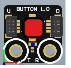
All this work for a button module? Like Gadgeteer, a button is a bad example if you think of it alone. You have a great set of modules, from displays to GPS to many sensors. A button is essential to complete the picture.
How do talk to the modules? Any device with i2c can talk to these modules and there is no need to a library! Very simple commands and registers will be listed on the modules docs. A button is just a single byte read. An addressable LED is just a 4 bye write (index, r, g, b)
What is the downside? This is a serial bus that maxes out at 1Mhz. The speed is sufficient enough for 1000 essential things but not for a 7" display. However, we think we will still offer the 7" display but with high level commands for drawing functions.
We will share the first module this week. It is called Big Bang, as it is where all other modules get created.
We want to share the Big Bang with you! But first, what do you like and dislike about this concept?
Trying to understand this - a module will include a processor and 2 connectors (upstream / downstream). For example for a module that uses a Microchip TC72 temperature sensor, the processor on the module will receive instructions via I2C and in turn communicate with the sensor over SPI ?
What will a mainboard look like ? may be processor, power and one or more I2C connectors ?
The board is a temperature sensor, regardless of what is in it. You are simply reading a byte over i2c to read the address.
In this concept, any board is a mainboard as the pressure is put onto the module. The mainboard only needs a single tiny connector… Or just a connection to i2c with only 2 wires.
Makes sense?
Yes !! - some ideas are popping in my mind - will wait to hear / see more.
But no gadgeteer sockets ?
Do you need it?
Here is a sample button for demonstration only. The connectors are likely to be on the back side.

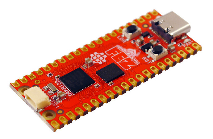
And here is an example mainboard, SITCore in this case but you can use anything with I2C.
The Gadgeteer concept is so good that it can’t help but keep coming back.
Long time since I’ve been here, hope everyone is well.
I have needed it so many times myself!! Good to see hear from you again.
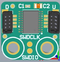
Preliminary schematics show that we can use $0.30 chip to do everything we need with 8 completely free pins to do whatever we need, plus additional 5 for backup.
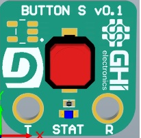
This is an example of a tiny module.


A button should have 4 holes. This one has 2 just to see how small things can be.
