@LucaP , thanks for the suggestion. I think that is probably the route I am going to go. I was already planning on a class file for each screen. Currently, all major functions are split into their own files as well. In regards to the network switch IC, I have my fingers crossed. The board is out for quote now for production so we will see what they come back with. I have added extra jumpers so I can fall back to just the SitCore ethernet port if necessary. I also have 2 different package size options on both I2C and SPI buses for FRAM memory so I can hopefully get around any shortages.
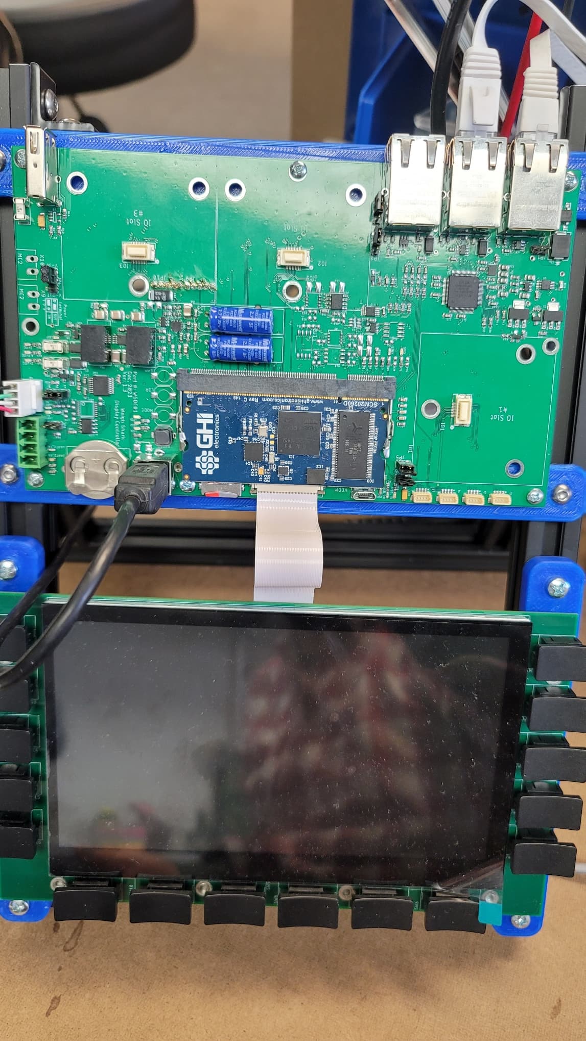
@mhardy, No worries, I welcome the discussion. Yes, the 2 blue caps are for power-fail backup. It gives me about 5 seconds to get files closed and saved. The SitCore, microSD, and FRAM are on their own 3.3V supply powered through that backup power supply so only the necessary components keep power.
The lower-left corner is a standard CR2032 for real-time clock and battery-backed RAM. I like the idea of a super cap but sometimes these devices can sit unpowered for 6 months and I was worried a super cap wouldn’t hold out.
The USB Type-B is the main programming port. I wanted a more robust port, especially if it needed to be accessed in the field. (These devices go in rock quarries and mines.) The bigger port is easier to keep clean and being thru-hole can handle a bit more abuse.
The micro USB is attached to an FTDI USB to UART going to UART 5. This was added as a backup debug/troubleshooting port.
USB host at this time and on this board is just intended for USB Flash drive for data logging, software updates, etc. I haven’t done too much work with it yet but what I have done it just kind of works. I do think there have been some compatibility issues with different formats or manufacturers of USB drives.
In the future, I am hoping we will see USB hub support and Cellular modem support.  That would make my cellular modem work MUCH easier.
The 3 ethernet ports are part of the 5 port ethernet switch. The SitCore’s ethernet port is capacitive coupled to one of the ports, giving me 3 external ethernet ports. (5th port not used.) Two ports can source power using passive PoE that is software controlled on/off and current monitored. This is primarily designed to power an Ethernet radio. The monitoring and control will allow us to cycle the power to the radio from the UI and monitor the current usage to see if it is truly powered. By reading the port stats from the network switch IC we can monitor link status and even measure the cable length to check for shorts. (Radios can sometimes be 100+ away from the device up high where they are inaccessible.) The 3rd port can take PoE in, again just the passive version, to power the whole board.
There is an RS-232 and RS-485 at the bottom left. Along with 3 expansion ports. Each port has a UART, I2C, and SPI bus going to them as well as a few I/O. Those will allow expansion for 4-20ma current loop outputs, digital I/O, more serial ports, cellular modem, wifi, etc.
The 4 ports along the bottom right are loosely based on the STEMMA standard. The first one is shared with UART5, the next one is I2C and the last 2 are UARTS. It is just a 4 pin plug with 2 data lines, GND and 5V. UARTS can be valuable down the road, you never know when you might need them so I like to have some way of accessing them for future use. One of the I/O option cards will be a dual serial port card. The card will use the UART at the port that it is plugged into and the second will come from a jumper cable going to one of these plugs.