I am not using the same lines, I removed the EEPROM to get this working before combining. Here is the data sheet:
I will switch to 2k
I am not using the same lines, I removed the EEPROM to get this working before combining. Here is the data sheet:
I will switch to 2k
sorry, by “lines” I purely meant the i2c pins on the microcontroller - so unless you removed the pullups with the eeprom, or unless you are using a different set of i2c pins on the micro, you don’t need to add the second pullups.
I removed the EEPROM pull ups. Switched out the 10k ones on the display for 2k. No luck with 100 or 200 kHz either. Am I doing the bytes write for the CreateWriteTransaction?
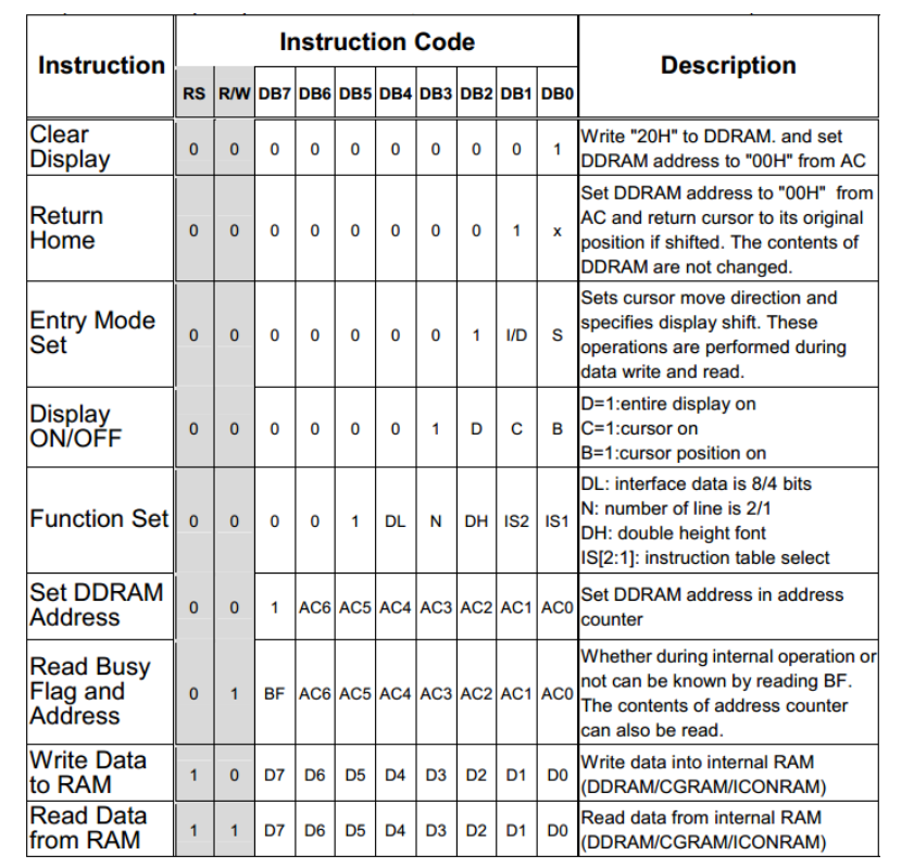
The data sheet says write to address 00 for commands and 0x38 sets a few register values for functionality. Am I misunderstanding that part?
That seems to match their initialisation code they supply.
I don’t know the exact display you use, but I think the initialisation looks quite the same for all with the same controller. Just one value looks a bit short for initialisation.
On page 43 and 44 is a init-sequnce for a serial-interfaced display with that controller.
When using I2C remember, that you have to write the values to address 0x00 (in the datasheet are no registers i the sample).
I linked the display I am using above it runs ST7036i, the first line of initialization is 0x38 which sets a bunch of settings ( all 3 NH displays I have used seem to use the same initialization and character codes)…there is more initialization code but I can’t get this first I2C transaction to work so no point in adding the 10 other transactions I have written out after. I have been writing to register 0x00 as well for commands.
@Brett I found a hardware mistake…the capacitor going between VOUT and VSS pins was shorting on my breadboard. I fixed it but still failing…maybe I friend something?
Ok the transactions aren’t failing anymore after I connected my scope to it…must be a loose wire somewhere as well. Now I just need to go back and 1) verify what I am initializing and 2) Fix my driver so I can write strings.
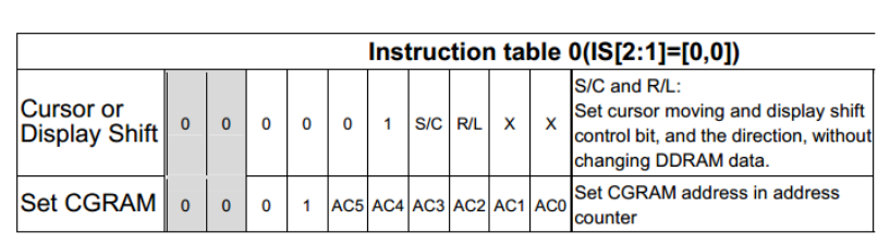
In their initialization code they send 0x38 then 0x39 - this is just two different versions of the same settings right? So i just need to do one version of function settings. They then send 0x14 which configures the cursor/display shift. Next they send 0x78 which corresponds to setting the CGRAM. WHAT THE HELL IS CGRAM?And why do they have AC2 AC1 and AC0 set as 0? They then send 0x5E which appears to be a different version of the previous CGRAM settings. I really need someone to explain the differences here. The next coommand is 0x6D which appears to be yet another CGRAM configuration, only one of these is needed correct? But what does each do? 0x0C is sent next which turns the display on and cursor off followed by 0x01 which is another version of the display settings. The final command is 0x06 which does “Entry Mode Set,”
@Brett You helped me redo my other I2C driver but not the Write(string) method of it. Can you take a look at it please?
using System;
using Microsoft.SPOT;
using Microsoft.SPOT.Hardware;
using System.Threading;

namespace DisplayTest
{

public class Display
{
    public  I2CDevice.Configuration I2CConfig;
    public I2CDevice I2C;

    /// <summary>
    /// Initializes a new instance of the <see cref="EEPROM"/> class.
    /// </summary>
    public Display()
    {
        I2CConfig = new I2CDevice.Configuration(0x3C, 400);
        I2C = new I2CDevice(I2CConfig);
        Thread.Sleep(100);
        I2CDevice.I2CTransaction[] transaction = new I2CDevice.I2CTransaction[1];
        transaction[0] = I2CDevice.CreateWriteTransaction(new byte[] { 0x00, 0x38});
        Thread.Sleep(10);
        if (I2C.Execute(transaction, 1000) == 0)
        {
            Debug.Print("Failed to perform I2C transaction");
        }
      //  I2C.Execute(transaction, 500);
        Thread.Sleep(10);
        transaction[0] = I2CDevice.CreateWriteTransaction(new byte[] { 0x00, 0x39 });
        Thread.Sleep(10);
        if (I2C.Execute(transaction, 1000) == 0)
        {
            Debug.Print("Failed to perform I2C transaction");
        }
        Thread.Sleep(10);
        transaction[0] = I2CDevice.CreateWriteTransaction(new byte[] { 0x00, 0x14 });
        Thread.Sleep(10);
        if (I2C.Execute(transaction, 1000) == 0)
        {
            Debug.Print("Failed to perform I2C transaction");
        }
        transaction[0] = I2CDevice.CreateWriteTransaction(new byte[] { 0x00, 0x78 });
        Thread.Sleep(10);
        if (I2C.Execute(transaction, 1000) == 0)
        {
            Debug.Print("Failed to perform I2C transaction");
        }
        transaction[0] = I2CDevice.CreateWriteTransaction(new byte[] { 0x00, 0x5E });
        Thread.Sleep(10);
        if (I2C.Execute(transaction, 1000) == 0)
        {
            Debug.Print("Failed to perform I2C transaction");
        }
        transaction[0] = I2CDevice.CreateWriteTransaction(new byte[] { 0x00, 0x6D });
        Thread.Sleep(10);
        if (I2C.Execute(transaction, 1000) == 0)
        {
            Debug.Print("Failed to perform I2C transaction");
        }
        transaction[0] = I2CDevice.CreateWriteTransaction(new byte[] { 0x00, 0x0C });
        Thread.Sleep(10);
        if (I2C.Execute(transaction, 1000) == 0)
        {
            Debug.Print("Failed to perform I2C transaction");
        }
        transaction[0] = I2CDevice.CreateWriteTransaction(new byte[] { 0x00, 0x01});
        Thread.Sleep(10);
        if (I2C.Execute(transaction, 1000) == 0)
        {
            Debug.Print("Failed to perform I2C transaction");
        }
        transaction[0] = I2CDevice.CreateWriteTransaction(new byte[] { 0x00, 0x06 });
        Thread.Sleep(10);
        if (I2C.Execute(transaction, 1000) == 0)
        {
            Debug.Print("Failed to perform I2C transaction");
        }
        Thread.Sleep(10);

    }

    /// <summary>
    /// Writes a one byte data at the specified address.
    /// </summary>
    /// <param name="Address">The address to write to.</param>
    /// <param name="data">The byte to write</param>
    public void Write(int Address, byte[] data)
    {
        byte[] byte1 = new byte[2];
        byte1 = new byte[] { (byte)(Address >> 8), (byte)(Address & 0xFF) };
        int length = byte1.Length + data.Length;
        byte[] payload = new byte[length];
        byte1.CopyTo(payload, 0);
        data.CopyTo(payload, byte1.Length);
        var xActions = new I2CDevice.I2CTransaction[1];
        //    byte1=[(byte)(Address>>8),(byte)(Address&0xFF)];
        xActions[0] = I2CDevice.CreateWriteTransaction(payload);
        Thread.Sleep(5);
        if (I2C.Execute(xActions, 1000) == 0)
        {
            Debug.Print("Failed to perform I2C transaction");
        }


    }

    /// <summary>
    /// Writes the string Text at the specified address.
    /// </summary>
    /// <param name="Address">The starting address to write to</param>
    /// <param name="Text">The text to write to EEprom</param>
    public void Write(int Address, string Text)
    {
        var xActions = new I2CDevice.I2CTransaction[1];
        byte[] buffer = System.Text.Encoding.UTF8.GetBytes("00" + Text);  // the "00" string reserves the room for the 2 bytes address that follows
        buffer[0] = (byte)(Address >> 8);
        buffer[1] = (byte)(Address & 0xFF);
        xActions[0] = I2CDevice.CreateWriteTransaction(buffer);
        Thread.Sleep(5);
        if (I2C.Execute(xActions, 1000) == 0)
        {
            Debug.Print("Failed to perform I2C transaction");
        }

    }
    /// <summary>
    /// Reads the specified address.
    /// </summary>
    /// <param name="Address">The address to be read</param>
    /// <returns>One byte from the EEprom</returns>
    public byte Read(int Address)
    {
        var Data = new byte[1];
        var xActions = new I2CDevice.I2CTransaction[1];
        xActions[0] = I2CDevice.CreateWriteTransaction(new byte[] { (byte)(Address >> 8), (byte)(Address & 0xFF) });
        Thread.Sleep(5);
        if (I2C.Execute(xActions, 1000) == 0)
        {
            Debug.Print("Failed to perform I2C transaction");
        }
        else
        {
            xActions[0] = I2CDevice.CreateReadTransaction(Data);
            Thread.Sleep(5);   // Mandatory after each Write transaction !!!
            if (I2C.Execute(xActions, 1000) == 0)
            {
                Debug.Print("Failed to perform I2C transaction");
            }
            else
            {
                Debug.Print("Register value: " + Data[0].ToString());
                return Data[0];
            }

        }
        return 0;
    }

}
}CGRAM - stands for “Character Graphics Random Access Memory” allows the user to define special supplementary non-standard character types that are not in the CGROM. You can load your own dot pattern shapes e.g. a rectangle into CGRAM and using certain reserved codes in DDRAM, call these up for display.
DDRAM - stands for “Data Display Random Access Memory” and is the working data buffer of the display. Each character on the display has a corresponding DDRAM location and the byte loaded in DDRAM controls which character is displayed.
ohhhh so they are just showing me examples of pre loaded dot patterns in that part of the initialization
The example codeshare driver has great abstraction of the primitives. I’d use that driver, and change the initialisation to reflect what you need (but honestly, they are probably compatible and you only need change the number of lines and characters in the macro definitions). Sure, while you’re testing it’s good to write your own simple code…
The example init does a number of transactions at once (no call to delay between) so why don’t you create a single transaction for them: I2C_out(0x14); I2C_out(0x78); I2C_out(0x5E); I2C_out(0x6D); I2C_out(0x0C); I2C_out(0x01); I2C_out(0x06);
I actually think you need to go back to the fundamentals - if your first transaction fails, that’s a sign of wrong address (no response from device) or a wiring issue. Yes, that could be caused by a short and failure.
I helped with the testing of the eeprom since I had one - send me a display and I’ll test it for you, as I don’t have anything that’s even similar.
@Brett I have the display working now, most of those transactions are unnecessary as half were just showing the other variation of each setting but they are all working now, it was a short. I just need to get my buffer for strings working properly.
awesome…
@Brett Thanks for the help!