@Brett The display cursor position resets itself after sending 8 characters on its own. I was taking advantage of that to not do an additional write to the display but I will give it a shot. The ToString() barrage was just testing the positioning on the display / making sure a shorter string was not getting passed.
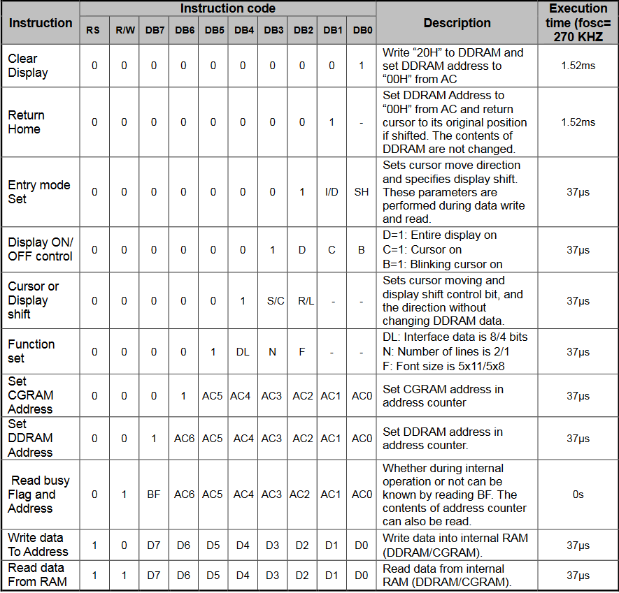
I am actually not sure what the command would be in 4 bit mode (DB0-DB3 unused), clear display and return home look the same to me.
Um, no, clearly not. Read the description. One clears DDRAM, one does not.
ok, so apparently you don’t understand the code? 4-bit mode simply uses two writes to write the 8-bit value.
I am not sure why you’d think that’s a smart test. Create a single string that you know doesn’t change, because who knows how the value you want to display could change while your code is executing. Plus, even if this was how you were testing it, the smart thing to do would have been to admit it made no difference, and go back to the streamlined version you really want to use…
So once that is clocked in the device knows that since it got two Nibbles and it is configured in 4-bit mode that it should reconstruct an 8 bit command by putting them together.
If it is the shift operator causing you trouble then let me try to explain what to expect given certain input:
The operators << and >> are bit-shift operators. They move the bits either left ( << ) or right ( >> ).
If a bit is “shifted out” of the value… the information is lost. Bits “shifted in” will be 0.
byte B = 0x20; // 0010 0000

byte ShiftedRightBy4 = B >> 4; // 0000 0010  - the one was shifted right 4 spaces. zeros filled in from the left.

byte C = 0x4F; // 0100 1111

byte ShiftedLeftBy5 = C << 5; // 1110 0000  - information that was shifted out is lost, zeros filled in from the right.
0xFF is an example of a hexadecimal value (notice the 0x in front)
0b00100110 is an example of a binary value (notice the 0b in front)
The prefixes are just ways of telling the reader what base the value is in. Sometimes they are set up to convey this information to the compiler as well… like we can use " 0x34 " as a value in our netmf apps.