I have a custom board using the G120 that works fine on the .NETMF and wanted to play with the latest release of TinyCLR OS 0.10. I have both the USB host and USB client on the board, that works fine in NETMF. I loaded bootloader v2 using TeraTerm per docs no problem loading it. Once I load the bootloader v2, then I connect using TinyCLR to update/load the Firmware, which works fine as you can see on the pic. Once reset, I am not able to see the board in TinyCLR config under USB to proceed to program it. More over, once I load the firmware (G120 Firmware v0.10.0.glb), I have some LEDs on the board, in 3-5 seconds all goes dim, as if “lights off” situation. Not sure what to make of it. If I boot using the LDR0 + reset, I get COM3, and I can use TinyCLR config tool to connect to it, as you can see on the image. I can then update firmware, or run, or Erase it.
I did the same process with my Cobra III, and was able to see it under USB as G120_G120, but not my board.
Question: Do I need to customize the G120 build to my board or maybe I am wrong?
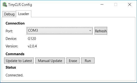
I loaded Bootloader v2 using the VCOM, as I only have USB on the board. I used the LDR0 + LDR1 => reset to start, and saw COM3 to connect in Tera Term. I used that, issued erase, and upload procedure for v2. After I reset the board now any time I do LDR0 = > Reset I can see COM3, and in TinyCLR config tool on the Loader tab, can connect to the board as shown in the picture. I can do the update via the Loader tab to latest, and that works fine.
Windows makes the sound when it recognizes the device, but I only see the COM3 no G120_G120 like I se on my Cobra III.
I do have G120, and looking at the schematic I see that we used P2.1 and is tied to GND by default. I can remove that easily to test, as that function on it is not critical on that port.
Should I not be able to still work in serial? This same setup works fine with NETMF no issues?
NETMF works fine on this board, have built 100s of these boards and have not had issues at all, and is why I am confused. Will try to remove the GND from that pin and look at it.
If I rebuild the G120 port of TinyCLR, can I update the debug button specs to change it? You have them currently as below, but I am thinking I can change it? If not, can I simply change the pin from 2, 1 to another one to make it work only to get it in USB mode?
… #define DEBUGGER_SELECTOR_PIN PIN(2, 1) #define G120_DEBUGGER_SELECTOR_PULL TinyCLR_Gpio_PinDriveMode::InputPullUp
…