Sorry I meant to say, you can always hire…
I was giving you options. You are however always welcome to ask any questions, any time.
Sorry I meant to say, you can always hire…
I was giving you options. You are however always welcome to ask any questions, any time.
Link to the display you bought? And given that there IS a driver for that model display, over SPI, you’ll need to tell us about wiring, and exactly what “no difference” means (its not very helpful to diagnose things remotely)
Thanks Ben
This is the display:
This is the details
and
containing zip files for driver and examples. It is C++. As you mentioned above , the C# version driver for TFT I am planning to use.
> None of the native graphics capabilities that your code uses will work on a Panda3 and an SPI based device. Panda3 doesn’t have the memory to be able to do this so GHI haven’t implemented full compatibility for the standard parallel LCD features that the G120 does.
> But all is not lost. You can write your own driver for whatever touch sensor your shield has if you need it. I haven’t seen one done that works universally but you may find one depending on what your display has. And if your screen is ILI9341you can use https://github.com/veccsolutions/Vecc.Netduino.Drivers.Ili93412 in netmf on Panda3
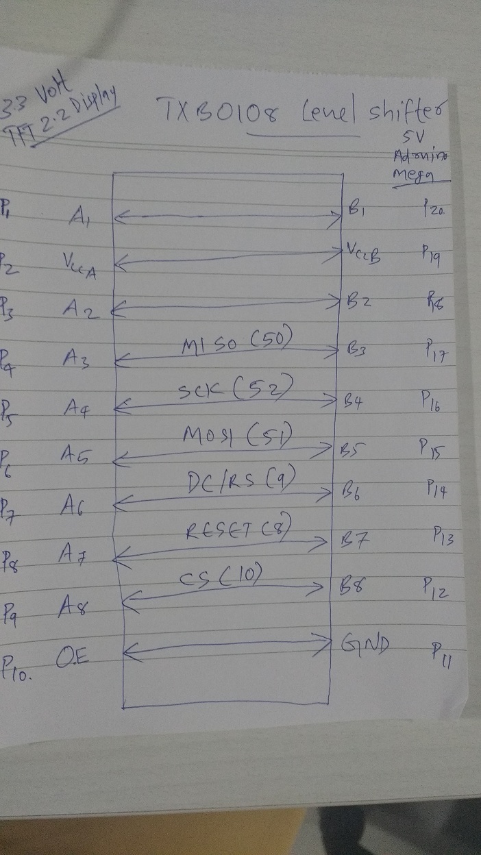
For Adruino, there is wiring diagrams
/*THIS LINK is for Adruino.
I searched for PANDA III Wiring for SPI display using IL9341 Did not get.
*/
So I really want a link to the actual display you have, not an instructable that just talks about some random device. Sure, they are mostly the same, but it’d be great to confirm 
But assuming the device is an SPI device, you just need to now use the driver that I’ve pointed out. The connections are very simple, and you just need the pins connected as per the constructor:
public Driver(bool isLandscape = false, Cpu.Pin lcdChipSelectPin = Cpu.Pin.GPIO_NONE, Cpu.Pin dataCommandPin = Cpu.Pin.GPIO_NONE, Cpu.Pin resetPin = Cpu.Pin.GPIO_NONE, Cpu.Pin backlightPin = Cpu.Pin.GPIO_NONE, uint spiClockFrequency = 20000, SPI.SPI_module spiModule = SPI.SPI_module.SPI1);
So in order, you need to select a CS pin, Command pin, Reset pin, Backlight pin, and the SPI connections, plus GND and VCC.
plus, my name is BRETT. Not sure where Ben came from !!
Dear “BRETT”
I was trying to make it working in Adruino first to understand the PIN connections and after 1 day’s effort(I am a beginer in embedded pgming)
I am posting the pin connections above to help someone. I tried to use the constructor tft = new driver(…) in Panda III.
But it is not showing anything.
I am posting the working adruino code here and the code in Panda III
In Adruino, digitalWrite(2,HIGH); is used for level shifter.
#include<SPI.h>
#include<ILI9341_due_config.h>
#include <ILI9341_due.h>
#include <SD.h>
#include “fonts\Arial_bold_14.h”
#define TFT_CS 10
#define TFT_DC 9
#define TFT_RST 8
ILI9341_due tft = ILI9341_due(TFT_CS, TFT_DC, TFT_RST);
gTextArea titleArea{ 10, 10, 300, 40 }; // define a 300px wide and 40px high title area
gTextArea descriptionArea{ 10, 60, 300, 80 }; // define a 300px wide and 170px high description area
gTextArea crackingArea{10, 150, 300, 80};
String cracking = “…”;
void setup()
{
Serial.begin(9600);
pinMode(2, OUTPUT);
analogWrite(7, 10); // PWM pin 7 to control backlight brightness 10/255
digitalWrite(2,HIGH);
bool result = tft.begin();
Serial.print("TFT begin successful: ");
Serial.println(result ? “YES” : “NO”);
tft.setRotation(iliRotation270);
tft.fillScreen(ILI9341_BLACK);
tft.setFont(Arial_bold_14);
tft.setTextLetterSpacing(5);
tft.setTextColor(ILI9341_BLACK, ILI9341_WHITE);
//Title area
tft.setTextArea(titleArea);
tft.setTextScale(2);
tft.clearTextArea(ILI9341_WHITE); // just to see where the area is
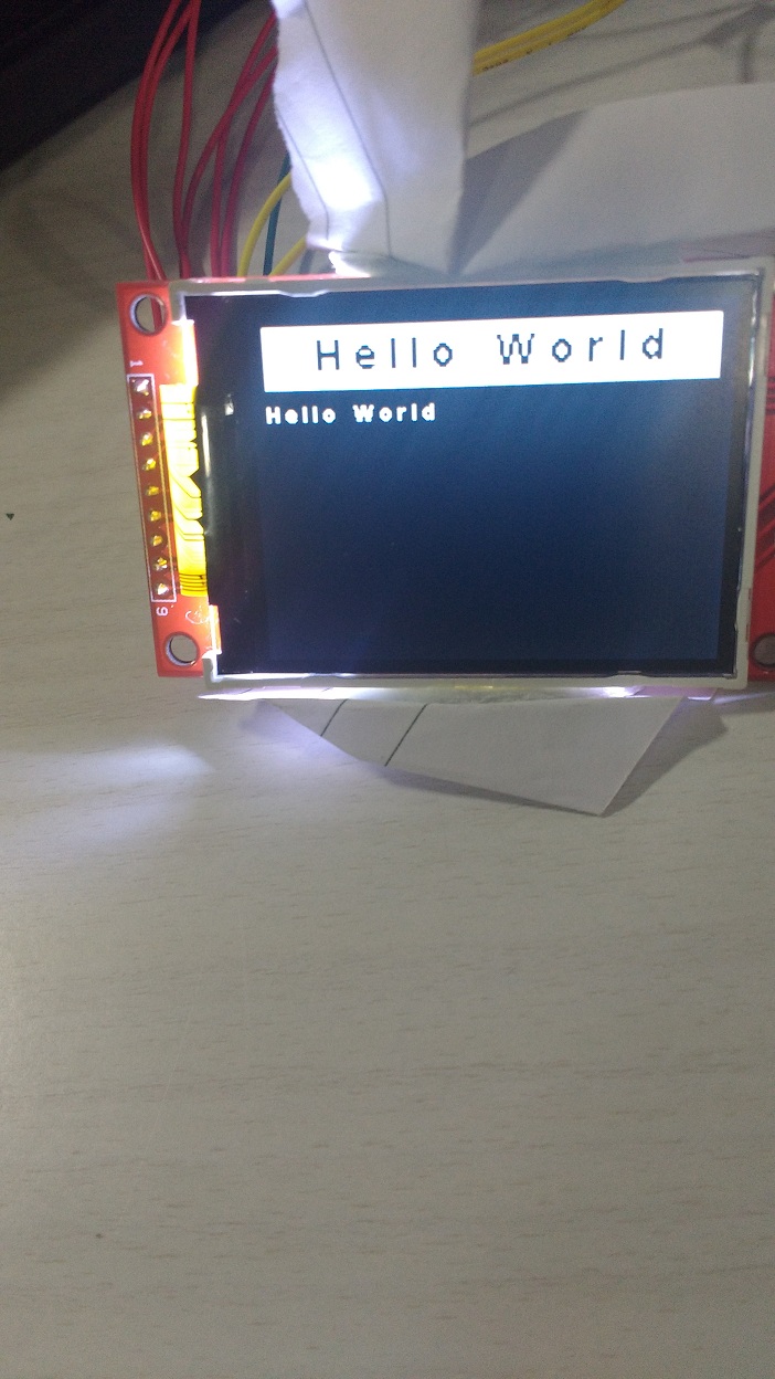
tft.printAligned(F(“Hello World”), gTextAlignMiddleCenter);
tft.setTextArea(descriptionArea);
tft.setTextScale(1);
tft.setTextColor(ILI9341_WHITE, ILI9341_BLACK);
tft.clearTextArea(ILI9341_BLACK);
tft.println(“Hello World”);
}
void loop()
{
}
PANDA III code.
///LEVEL SHIFTER
1. OutputPort LED;
2. LED = new OutputPort(GHI.Pins.FEZPandaIII.Gpio.D2, true);
3. LED.Write(true);
var tft = new Driver(isLandscape: true,
lcdChipSelectPin: GHI.Pins.FEZPandaIII.Gpio.D5,
dataCommandPin: GHI.Pins.FEZPandaIII.Gpio.D6,
resetPin: GHI.Pins.FEZPandaIII.Gpio.D7,
backlightPin: GHI.Pins.FEZPandaIII.Gpio.D9);
var font = new StandardFixedWidthFont();
tft.ClearScreen();
while (true)
{
tft.DrawString(10, 10, "Hello world!", 0xF800, font);
tft.BacklightOn = true;
}
I used SPI 1 default.
Thanks
Ramb
Please confirm your wiring. What is CS connected to on the Panda? DataCommand? Reset? MOSI? MISO? SCK? Once you do that I’ll dig out a Panda3 and a display and demo it…
I will explain
TFT2.2---------------------------------------LEVEL SHIFTER--------------------------------Panda III
MISO-----------------------------------------------B3-----------------------------------------------PIN 12
SCK--------------------------------------- B4--------------------------------------- PIN 13
MOS--------------------------------------- B5--------------------------------------- PIN 11
And following set via constructor
DC/RS--------------------------------------- B6--------------------------------------- GHI.Pins.FEZPandaIII.Gpio.D6
RESET--------------------------------------- B7---------------------------------------GHI.Pins.FEZPandaIII.Gpio.D7
CS------------------------------------------------B8---------------------------------------GHI.Pins.FEZPandaIII.Gpio.D5
And I removed the backlight pin from constructor
///LEVEL SHIFTER
OutputPort LED;
LED = new OutputPort(GHI.Pins.FEZPandaIII.Gpio.D27, true);
LED.Write(true);
        var tft = new Driver(isLandscape: true,

                             lcdChipSelectPin: GHI.Pins.FEZPandaIII.Gpio.D5,
                             dataCommandPin: GHI.Pins.FEZPandaIII.Gpio.D6,
                             resetPin:  GHI.Pins.FEZPandaIII.Gpio.D7
                             );
        var font = new StandardFixedWidthFont();
        tft.ClearScreen();
        while (true)
        {
            tft.DrawString(10, 10, "Hello world!", 0xF800, font);
            tft.BacklightOn = true;
        }
I am getting a blank white screen. When code is running, I just noted, a blink(only one time) in the screen.
Here’s my exact same sample code. I haven’t re-run it to prove it still works, but don’t expect that it’ll have changed at all since it was working when I was testing my change for the ILI9341 library. Edit: I may need a few days before I’ll have time to test deploy for you…
        lcd = new ILI.Driver(isLandscape: true,
            lcdChipSelectPin: GHI.Pins.FEZPandaIII.Gpio.D7,   //Panda3 D7
            resetPin: GHI.Pins.FEZPandaIII.Gpio.D1,
            dataCommandPin: GHI.Pins.FEZPandaIII.Gpio.D4,
            backlightPin: GHI.Pins.FEZPandaIII.Gpio.D5,
            spiClockFrequency: 40000,
            spiModule: Microsoft.SPOT.Hardware.SPI.SPI_module.SPI1);

        font = new ILI.StandardFixedWidthFont();

        lcd.BacklightOn = true;

        lcd.ClearScreen();
        lcd.DrawString(x_pos, y_pos, "Hello Panda 3 !", 0xFF00, font);

        while(true)
        {
            lcd.ClearScreen();
            y_pos += 20;
            if (y_pos > 220)
                y_pos = 20;
            lcd.DrawString(x_pos, y_pos, "Hello Panda 3 !", 0xFF00, font);

            Thread.Sleep(20);
}Where are your GND and power wires ? I have powered my device from 3v3 directly, so don’t need to use level shifters - have you tried it in that configuration?
Yea,
Brett. I spent some time in level shifters. It was not required. Panda III already has a regulator which outs 3.3 So, I removed the level shifters and connected directly.
GND I given to Panda III ground and I used 3.3V Vcc out from Panda III to display. RIGHT NOW, no LEVEL SHIFTER.
Ramb
as discussed on email, I have my code working fine on a Panda3 and 2.8" ILI9341 display, and you have my full project, so it then comes to wiring and/or display issues not code.