Asside from the “Beginners Guide to C# and the .NET Micro Framework”, which covers:
6.2. Digital Inputs
6.3. Interrupt Port
6.4. Tristate Port
I’m still a bit lost about how I would go about soldering a button onto this board… sure I could tear up the LDR pins and solder a wire to them, but I know this is wrong.
I would like to know more about:
which pins on the side of board should I use, don’t I need to use a GND (ground) for a button…? Ihat if I have two buttons, can I solder two wires to the GND pin (one for each button)? I’m an intermediate programmer, but I’m a novice at: .NETMF, C#, .NET, embedded devices, VS C# Express, and soldering… I would really appreciate some advice or maybe a tutorial…
I imagine it happening like this:
I take my buttons
called: “Normally Open Off - (On)” if that makes any difference… I suspect it will when it comes time to set up the Interrupt Ports
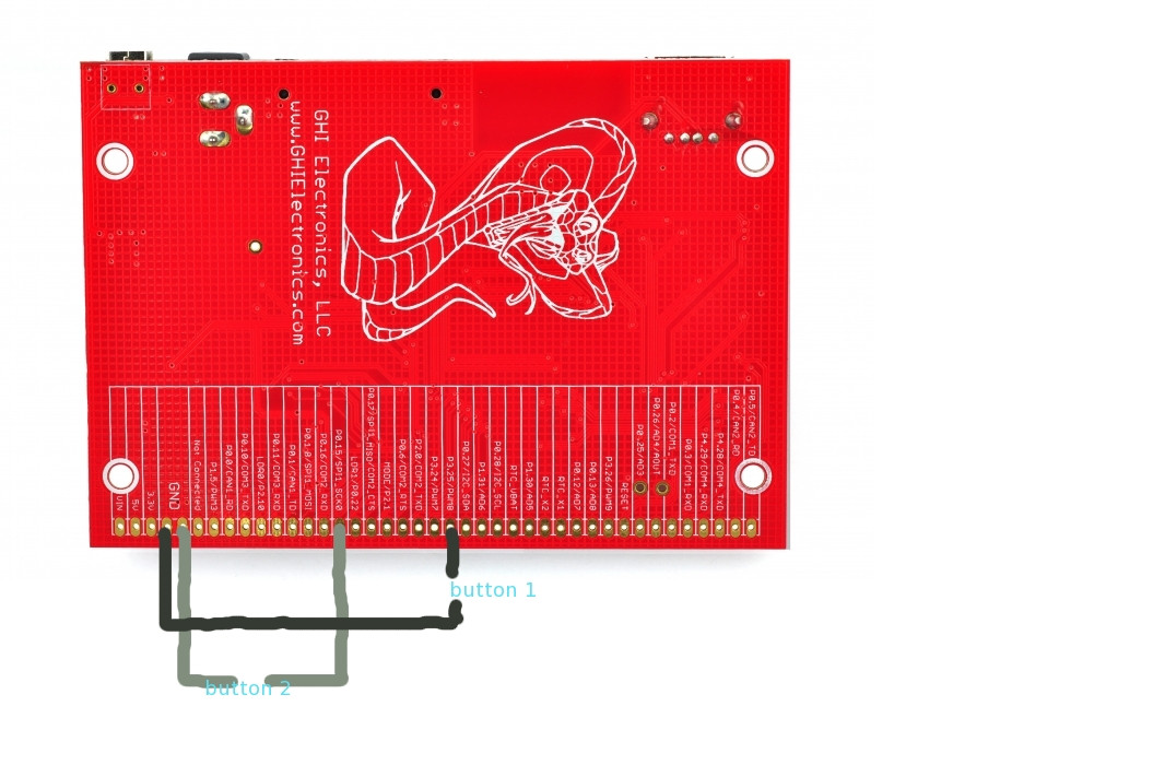
and solder them onto the pins on the side of the board like so:
but, that doesn’t make sense… actually, I don’t think I need to use a ground… it should maybe look like:
Output Port 1 [pick a pin] ===> button 1===> Input Port 1 [maybe interrupt port?]
Output Port 2 [pick a pin] ===> button 2===> Input Port 2 [maybe interrupt port?]
Maybe someone can point me in the right direction?
The other question would be, what are you trying to achieve? Perhaps you can think about how you’re likely to want to connect/disconnect the switches? You could for instance solder male or female 0.1" headers onto the edge connector and then the opposite onto wires from your button. Or you could design a PCB that had the pads you needed and plugged onto the same headers. Many options, but it’d be great to hear what you’re wanting to get out of this.
Brett, excellent question:
The board is intended to go on a door and the serial camera module is meant to replace the lens that would normally go on a peek hole (to see the person on the outside of the door, if there is one). I have two buttons:
One is intended to replace the doorbell [Normally Open Off - (On)] button
The other button is actually a magnetic reed switch [Normally open without magnet, Normally closed without magnet] … maybe that’s a typo or maybe i’m incompetent? lol
The magnetic reed switch is intended to let me know when the door is open/closed. You might find this component on security installations in retail shops/stores on the front door.
OK, so either way I would see that you will probably NOT want to hang your Cobra 2 on the door - easy theft target ! So then I reckon you will want wires of some length for everything including your camera.
The n00b’s book (sorry ) is actually mainly in the 4.1 way of thinking. 4.2 that you have (and need to support G120) has changed a few things. The GHIelectronics.netmf.fez is now something like GHI.Premium.xxxx so you should update your USING statement and listed REFERENCES with the relevant items - for G120 Cobra2, the references I have for a project are GHI.Premium.Hardware.G120 and GHIElectronics.Gadgeteer.FEZCobra_II
I am actually using three of these boards, so if someone opened the door to steal the board on the inside of the front door, they will almost surely have their picture taken multiple times (since there will be a camera facing the door from the inside of the house, and a camera facing the door from the outside of the house (which is well protected)).
Your point is well taken, I have already acquired some wire to solder to the switches + pins with the help of an electrician who said it can handle 3.3V (like mentioned in the tutorial). It’s also insulated, for whatever that’s worth it’s not some wimpy jumper
The only piece of information I’m missing is how to find out which pins are interrupt capable. That would put the nail in the coffin of this post/thread.
Edit:
I went through the inline documentation for GHI.Premium.Hardware.G120.Pin.* (kind of like JavaDoc), and all of the pins have the same comment: “GPIO Pin”.
Edit 2:
OK… since the pins are on the processor, I should be looking at the G120 Module resources…
right here: http://www.ghielectronics.com/downloads/G120/G120%20Module%20Brochure.pdf
it says: GPIOs P0_x and P2_x are Interrupt Capable. All pins are 5 volt tolerant.
great to hear you’re sorted. Let us know if you have other issues and I’m sure someone will be able to help guide you (perhaps not answer you, but talk it through for sure )
 ) is actually mainly in the 4.1 way of thinking. 4.2 that you have (and need to support G120) has changed a few things. The GHIelectronics.netmf.fez is now something like GHI.Premium.xxxx so you should update your USING statement and listed REFERENCES with the relevant items - for G120 Cobra2, the references I have for a project are GHI.Premium.Hardware.G120 and GHIElectronics.Gadgeteer.FEZCobra_II